

This paper explores some of the issues facing the development of an interactive modeling system that uses a simple Indycam to aid in the capture of shape and color of a desktop-sized object. The generated models may be crude by laser-scanning standards, but the method should be easily accessible to anybody with a digital camera connected to a computer.
There is an extensive literature on computer vision and algorithms for automatically calculating shape from images. These techniques are beyond the scope of this paper. Instead, I wish to focus on simple algorithms that enlist the user to interactively solve the "hard" vision problems, such as finding silhouettes, etc.
The recent "multimedia" craze has led to a proliferation of digital cameras attached to computers, such as SGI's Indycam. For a PC, a color camera can be bought for under $200. In the near future, digital cameras may become as ubiquitous as today's computer speakers. This paper seeks to explore one possible use for these cameras, to assist in generating models for graphics.
It is common for people in computer graphics to be interested in generating models of real-life objects. However, scanners (such as Cyberware's laser range scanners) are still expensive and inaccessible to the general public. As a result, most people still find it tedious to generate complicated realistic models.
For example, I browsed through some of the scenes that students have generated for Stanford's cs348b raytracing contest. In general, the models tended to be composed of basic geometric primitives, such as spheres, boxes, and surfaces of revolution. Some complex models were procedurally generated, such as this golf ball. The complex hand-generated models, such as this guitar, were rare. Furthermore, texture maps were mostly used for planar surfaces (or cylindrical labels, that could be flattened for scanning).
Here's a few selected examples:
These models are good, and the raytracing effects are often dramatic. But how much time did the students spend to model these objects? The oranges were volume-rendered with a volume density function. The rest of these objects were modeled by hand. Presumably, the students spent some time trying to get the shape and proportions right.
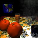
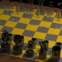
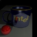
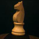
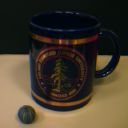
Here's a few similar real-life objects, photographed with an Indycam:
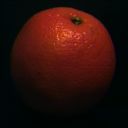


How might we harness these images to guide the modeling process?
In order to use the Indycam, we must find some way of mapping the pictures to the 3D model that we are generating. This process, called camera registration, involves correcting camera distortion ("calibration") and determining the position and orientation of the camera.
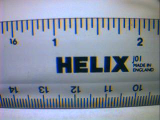
This picture shows some of the worst distortion artifacts of the indycam. First, the geometric lens-distortion causes the ruler to appear bent. This can be corrected with an inverse warp, which will map the pixels back to a pinhole camera image [8].
Second, on the bottom of the ruler, we get color aliasing due to the spacing of the R, G, and B sensors on the camera's CCD array. This may be difficult to fix in software. We can compensate for this by putting the camera slightly out of focus, or by moving the object closer until the features appear large enough that they don't alias (Like the word "HELIX").
Third, we can see that even the word "HELIX" has some color distortion. It tends to have a reddish fringe on the right side of each letter, and a bluish fringe on the left side. We may be able to partially compensate for this effect with some image filtering.
Finally, the picture shows some other minor artifacts, such as vignetting (a darkening near the edges of the picture).
Another approach is to completely automate camera registration. One example of this was demonstrated in the Lumigraph [3], by Steven Gortler et. al. They used a backdrop painted with circles. These visual markers enabled the program to calculate the position and orientation of the camera, without user interaction:
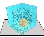
Debevec's approach would probably work better with my proposed modeling system. Rather than having a specific, fixed backdrop, the user will be able to use any identifiable geometry available (such as a cube in the scene) to align each camera view. This might require a few initial iterations to get the model correct for the identifiable geometry. However, if an object in the scene has a known shape (such as a Rubik's cube, which is 2.25 inches on a side), then we could start with known geometry and get accurate camera positions immediately.
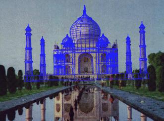
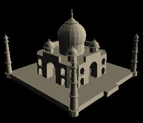
These pictures show a single source image of the Taj Mahal, and the 3D model generated by Debevec's program, facade. Basic geometric primitives (i.e. "blocks") are good for modeling many of the features found in architecture, such as flat walls and objects of revolution. They often have identifiable edges that enable easy correspondences between the picture and the model. Currently, facade is able to handle polygonal walls, surfaces of revolution, and archways.
Facade's approach takes strong advantage of constraints and symmetry. A symmetry constraint, for example, makes it possible to model Berkeley's Companile, Stanford's Hoover Tower, or even the Taj Mahal from a single photograph. (Some of the texture may be missing in these models, but the geometry is complete.)
Facade is well-suited for architecture, where most objects can be modeled with primitives. However, it is still difficult to be able to handle irregularly shaped free-form surfaces. One possible approach to this problem is to handle the object volumetrically. Szeliski [6] showed that an octree volumetric representation can be an efficient way to generate shape from silhouette edges.
Here is an example of a model generated from volumetrically carving away silhouette edges, generated by Paul Debevec with just 5 telephoto pictures of his car:
Both polygonal and volumetric representations offer advantages. The polygonal and geometric primitives are easily manipulated. They generally have a limited number of degrees of freedom, and thus can be completely specified quickly from a few images. Once a few geometric primitives are aligned, they can easily act as visual markers for camera registration. Furthermore, polygons are easily stored in model files, such as Inventor's .iv format.
On the other hand, volumetric representations are more manageable for free-form surfaces, of arbitrary shape and topology. The silhouettes can carve away the volume, leaving the line-carved hull of the object. Due to this manageability, both the Lumigraph [3] and Curless & Levoy's Volumetric Modeler [1] use voxel representations.
One major drawback of modeling objects volumetrically is that we
need to convert the output to a reasonable format. Typically,
this is done by generating an isosurface of the volume. However,
since our voxels will only have binary data (inside the object,
or outside the object), the resulting polygon mesh will have
sharp facets. To solve this, we will need a filter such as
Taubin's polygon mesh smoothing algorithm [7], in order to get
reasonable surface normals and fewer polygons. For some nice
examples, see
Bill Lorensen's excellent
page on smoothing.
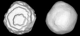
It seems to me that the best approach would be a hybrid method, incorporating both geometric and volumetric objects. Polygons and geometric primitives would be used whenever possible. These are easily manipulated, and often serve as good visual cues for registering the camera. These primitives also make it easier to deal with constraints, such as specifying symmetry or objects of revolution.
However, when a scene contained some strangely shaped object, the user could specify a bounding box around the object, filled with "volumetric clay." As each silhouette view carved away the "clay" voxels, the object would take shape. At the end of the modeling session, a polygon mesh would be generated from the volume isosurface, and then smoothed with Taubin's mesh smoothing algorithm.
All of the modeling techniques described above have been implemented in different modeling systems. It is fun to ponder, however, what other techniques can be used to assist the modeling process. For example, Robert Zeleznik's SKETCH program [9] offered a glimpse of the expressive power of a well-designed modeling interface. It makes the process of generating rough models, such as this, quickly and painlessly:
It would be fascinating to see such a modeling tool assisted by a video camera. The camera could conceivably make it easier to capture the proportions of a real model, as well as a texture map for the model. In some sense, the camera adds an element of preciseness that Zeleznik was attempting to avoid. On the other hand, the camera frees the user to concentrate on the general structure of the model, and the camera will clean up all the little details.
Another interesting idea would be to use "probes" to "carve out" the concave surfaces of a volumetric model. A probe could be as simple as a cube (that has already been modeled). Then, in each picture, the modeling program could (from a few line correspondences) determine the position of the probe, and "carve out" any voxels occupied by the probe. This would enable the user to model concave surfaces that would be inaccessible to silhouette carving.
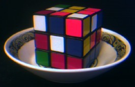
A cubic probe explores the depths of the bowl. Line-of-sight
carvings, with an "object of revolution" constraint, could almost
carve out the entire inside of this bowl from this single image.
A probe could take many shapes. The critical factor is that the probe's position should be relatively easy to calculate from the image. For example, cubes and spheres would make good probes. It might also be possible to make probes out of clay. A clay probe could be molded to a concave recess on an object. When it was removed, the (hopefully) convex clay probe itself could be modeled. This volume could then be aligned with the object and subtracted, to carve out the recess.
Color acquisition, at first glance, appears to be a straightforward application of camera-aided modeling. The camera can paint texture maps onto the object, which often increases the realistic appearance of an object by an order of magnitude.
Currently, most texture maps are acquired with a flatbed scanner, which are only good at acquiring texture maps of flat (or flattenable) objects. A camera can make it possible to put a texture map on any object. Ideally, if we intend to create a standard model of the object, we want to texture map the object with its diffuse color. However, there are several issues to consider when trying to acquire this diffuse color:
For the purposes of a user-friendly, accessible modeling package, it would probably be too difficult to require controlled lighting conditions. As a result, it would be difficult to fully implement Sato and Ikeuchi's methods. However, it is important to be aware of the possible sources of error, and compensate for them whenever possible.
For example, one simplified approach might assume that the world can be described, as a rough approximation, as "light on top, dark on the bottom". Consider, for example, a typical place where modeling might occur -- a computer lab. Above the object, multiple fluorescent lights on the ceiling illuminate the object from many angles. Below the object, the desk reflects only a fraction of the incident light. The resulting gradient of diffuse illumination can be seen on some of my test images at the top of this page -- the orange, Advil bottle, and chess piece are all brighter on the top than on the bottom. From the model geometry we can make an estimate of the surface normal at every point, and we can use that normal to estimate how much illumination that point is receiving.
This would partially correct for differences in diffuse illumination, but would not correct for specular reflection. To handle specular components, we would probably want to gather several (weighted) samples of that point from different angles. We could then use some function that would filter away the outliers caused by shadows and specular highlights. For example, we could take the weighted median of the samples for each point. This would likely ignore an excessively bright sample from a specular highlight, or an excessively dark sample from a shadow.
We would want to assign weights to the samples in an image, for several reasons. First of all, the sampling density varies with camera proximity and surface incident angle. This weighting is analogous to Brian Curless' weighting functions for each range image ray [1]. It assigns more weight to samples that strike the surface perpendicularly, and fades to zero at the edges, leading to a smooth transition between different views.
In the end, we want to be able to write out a texture mapped polygon model. For polygon & geometric primitive models, the color could be accumulated as a texture map. However, if we are modeling freeform voxelized geometry, each voxel will record a single color. Then, when we convert to a micropolygon mesh, each polygon vertex may have a color. If we simplify the mesh during smoothing, then we will probably have to create texture maps on the larger polygons to maintain our spatial color resolution.
By combining several of the ideas developed in recent years, it now appears that all of the pieces are in place to build a reasonable camera-assisted modeler. Debevec has already shown that such a system is feasible for architectural models. With a volumetric approach, I doubt that free-form objects will be far behind.
Clearly, though, the task of writing a reasonable modeling system is far from trivial. None of the steps are insurmountable, but neither are they trivial. Each step of the process should be written in a modular approach. In that way, a basic, low-automation proof of concept could be developed in a reasonable amount of time, and improved functionality and automation can be added as time allows.