CS 348b: A study in non-linear ray tracing
|
Downloads: Other Links:
|
Motivation
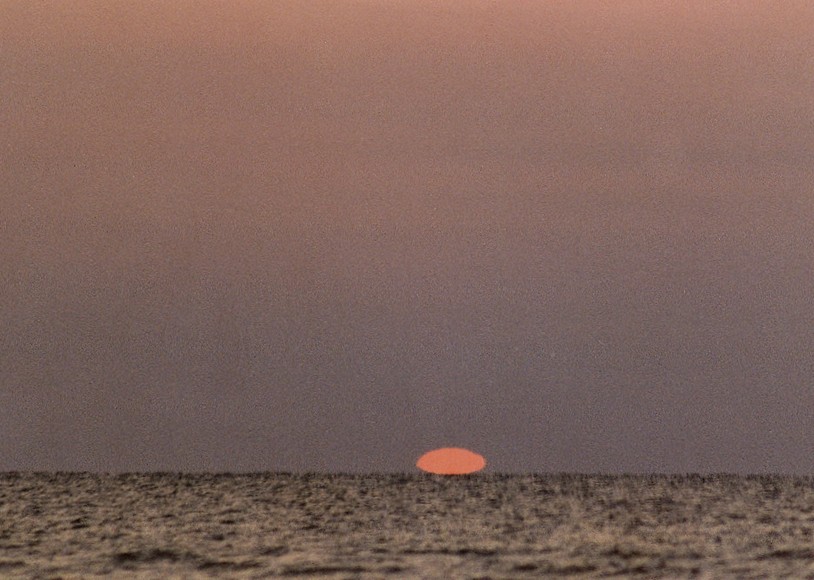
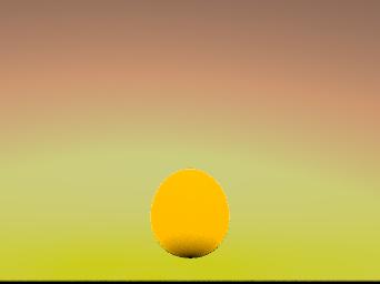
Mirages are caused when the atmosphere experiences a rapid density shift. The result is that rays passing through the atmosphere bend into a parabolic shape. This presents an interesting problem for ray tracing, as many ray tracers (including PBRT) assume rays follow a straight line path. Generalizing this assumption amounts to finding the path of a particle in a force field. Several solutions to this problem have been described. Our results are presented below in two sections:
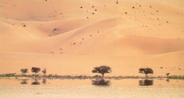
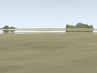
Methods We studied a number of methods to trace rays in non-homogenous media. In each case we assumed that the refractive index is a function of height. (1) Slab method: In this case, the whole scene is divided into a number of horizontal layers, each with a constant index of refraction. Every ray is refracted several times as it passes through the scene. Snell's law is applied to compute the new direction whenever the ray travels from one layer to another. 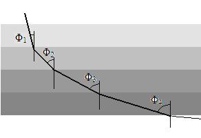 (2) Length method: The drawback to the slab method is that any nearly horizontal ray will have to travel a great distance before it gets refracted. In order to overcome this problem, ray trajectories are recalculated at fixed length intervals. This method is very similar to the slab method, except that the slabs have varying width. 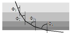 (3) Exact method: This implementation traces rays based on an exact analytical solution. Suppose the refractive index (RI) varies with height as follows: The snell's law governing the change in direction of ray is given by: Let θ be the direction of ray in x-y plane. Then Φ = π/2 - θ. Let Φi and Φt be the angle of incidence and refraction respectively at any point on the ray. 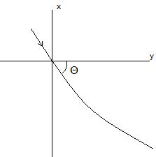 When given the value of x at any point, y can be obtained by plugging in the appropriate values in the following equation: a = no + m*x b = no*sin(Φo) (4) Euler method: We evaluate the value of x at fixed, equally spaced grid points and find the y for the corresponding x increment. Let xo be the initial value of x and h be the step size (or grid size).Then x at any grid point is given by: The RI at depth/height xn+1 is computed by using equation (1). Then snell.s law is applied to compute the angle of refraction at point(xn+1 , yn+1): Finally the computed angle of refraction is plugged in the following equation to obtain the corresponding y: (5) Runge-Kutta: This is similar to Euler's, but the new y values are computed by considering the ray direction at three intermediate points between (xn,yn) and (xn+1 ,yn+1). Let f(xn, yn) = tan(Φnt) where Φnt is the angle of refraction at the point (xn,yn). As shown before, Φnt for any point is computed using equation (4). We use fourth order runge kutta to compute the new points: k1 = h* f(xn, yn) k2 = h* f(xn + h/2, yn + k1/2) k3 = h* f(xn + h/2, xn + k2/2) k4 = h* f(xn + h, xn + k3) yn+1 = yn + k1/6 + k2/6 + k3/6 + k4/6 Results We examined the five methods above by implementing them in MATLAB and comparing their accuracies. Based on this study we chose two methods, slabs and Euler's, to implement in PBRT. The following images were rendered using the slab method. In addition, we implemented a handy MATLAB debugging script to show us the path of the rays. All the heightfields (sand, water, icebergs, and mountains) were generated using a diamond-square fractal algorithm. Inferior mirages This is the classic mirage example. In an inferior mirage, rays passing close to the horizon get reflected upwards through total internal reflection. What is often described as pools of water in the desert is in fact the reflection of the blue sky onto the ground. Because of the way light refracts in this type of mirage, the landscape appears to sink. 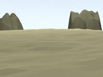
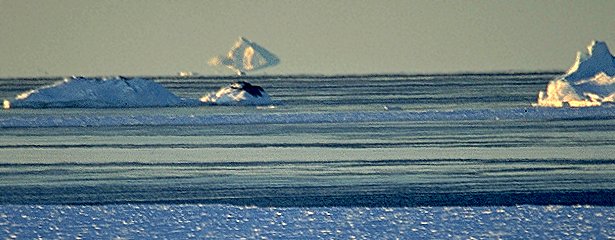
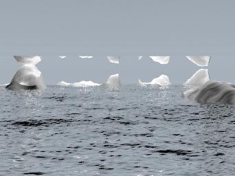
Click on the images for a full-size version. Superior mirages Superior mirages occur in cold climates. In a superior mirage, surface ice cools the air as it reaches the surface. Upwards reflections are created when rays that are increasing in height get reflected downward through total internal reflection. Occaisionally, the combined iceberg/reflection looks like a large land mass. "Crocker Land", a mountain range that appeared on arctic maps from 1909 to 1916, was nothing more than a superior mirage. 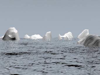
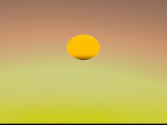
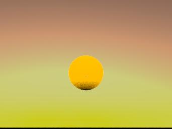
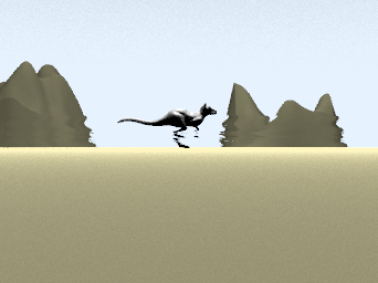
Click on the images for a full-size version. Towering and stooping Besides creating reflections, mirages can cause objects to appear compressed (stooping) or stretched (towering). The first two images demonstrate stooping. The last image demonstrates towering. Notice how the object appears to move in addition to being distorted, a phenomenon known as "looming". Throughout history, looming has led sailors to describe ghost ships sailing in midair above cold waters. 
Click on the images for a full-size version. Heat distortion Heat distortion is caused by rays passing through local air pockets of different densities. This differs from the previous three examples because the index of refraction is a three dimensional function, as opposed to just varying with height. In the image below, we chose the phenomenological approach of jittering the rays. 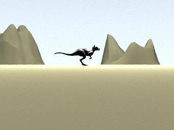
Click on the images for a full-size version. Comparison of methods We compared the five methods for different step/slab sizes and step/slab count. The following table describes the accuracies we found:
The associated colors are: Magenta - exact method Green - Euler method Black - Runge-Kutta Blue - Slab method Red - Length method 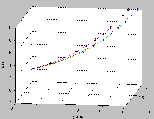 Parameter values(n=10,h=0.5) 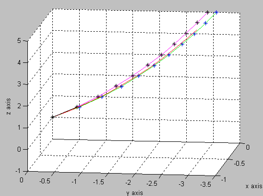 Observations and conclusion One of our biggest challenges was figuring out how to incorporate curved rays into PBRT. Early attempts included volumetric modeling, new camera types, and a new distribution field. We discovered that by breaking up our ray into small segments (each of which is linear) we could avoid extensive modifications to the PBRT core. We also ran into problems when placing objects in the scene. Mirages are inherently dependent on having precise geometry, and many frustrating attempts were made to place objects and the camera at the correct distance and orientation. This ended up being a trial-and-error process. If we had more time, it would have been interesting to implement a more sophisticted model for heat distortion. Currently our system only handles index of refraction that varies with height. By incorporating a three dimensional index of refraction, we can model distortion from arbitrary heat sources (such as a stove top or car exhaust). Division of labor Since the two parts of this project required implementing the same algorithms twice (in PBRT and MATLAB), both partners contributed to all sections. However, Pankhudi focused more on the MATLAB and the mathematical aspects and Itai focused more on the PBRT sections. While the final PBRT implementations ended up being compact, considerable effort was spent on the failed attempts mentioned above. References [1] M. Berger, T. Trout. "Ray tracing mirages". IEEE Computer Graphics and Applications, 11(5), pp. 36-41, May 1990. [2] Seron, F.J. "Visualizing sunsets through inhomogeneous atmospheres". Computer Graphics International (CGI'04). 2004. [3] J. Stam, E. Languenou, "Ray tracing in non-constant media". Proceedings of Rendering Tecniques '96, pp. 225-234, 1996. | ||||||||||||||||||||||||||||||||||||||||||||||||||||