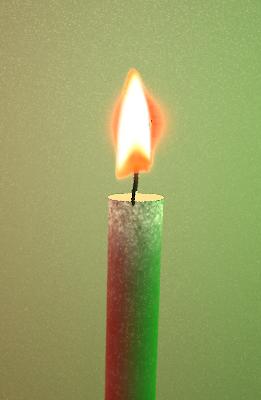
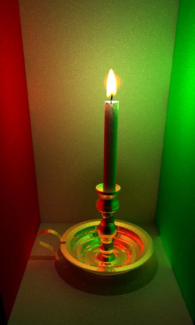
versus
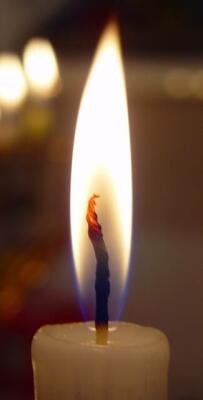
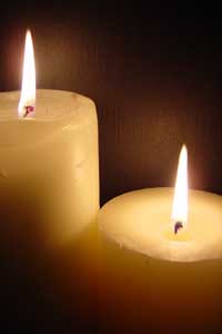
Main Goal:
CS348b - Spring 2004
Modeling a candle
Our final pictures:

versus

Main Goal:
Scene setup
We obtained our model for the candle from http://www.3dcafe.com/asp/househld.asp. The website credits David Barry as the creator of the model. We took the mesh and made a few minor modifications and then exported it to .rib format. We then used rib2lrt to get a file usable by us. One complication arose when we began translucent effects. The rib2lrt function makes each triangle in the .rib file a triangle mesh rather than making each object a triangle mesh composed of many triangles. To fix this we wrote a simple script to fix the problem so we could know the geometry of the whole translucent object for sampling. Finally we made a scene file from this model and the specifications of the Cornell Box. We stuck the wick in later to complete the scene. All the surfaces use the "matte" material in pbrt except for the candle holder which is "shinymetal".
Flame
Since we were going to model a non-turbulent flame, we decided to do away with doing turbulent flow simulations, and just derive the shape of the flame from a texture. We initially modeled the flame as a volume region that approximated the properties of a blackbody radiator--an object with light absoption and emittance properties, but no scattering properties. In order to get a full-bodied 3D flame from a 2D texture, we made the density of the volume a function of both the color and the intensity of the texture. We got the best results treating the volume as a volume grid and setting the color at each grid voxel to be some color derived from the texture, multiplied by its intensity. The emitance coefficient was set to the voxel color, the absorption coefficient to the hue inverse of the color (so if we wanted red, it would absorb blue and green), and the scattering coefficient to zero. The color inversion was done by converting the RGB components of the color to HSV, flipping the Hue component, and then reverting back to RGB.
| original texture | emissive, absorbing, but non-scattering volume | ||
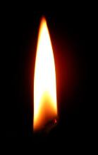 |
+ | 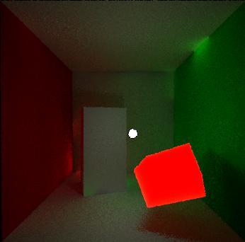 |
= |
flame! (well, sort of...)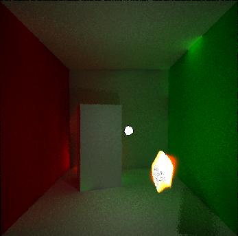
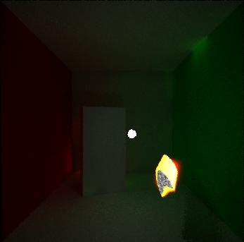
In order to get a more cylindrical flame, we used some coarse image processing techniques to find an approximate spine for the flame, and then revolved the color of the flame along this spine. The spine point for each y-coordinate was found by taking the leftmost and rightmost bright pixels in a row and averaging the x-coordinates of the two. The first approach to doing the revolution was done by revolving both the colors and the intensities of the texture around the spline point. Care was taken to interpolate texture values so that the revolution would appear smooth.
revolving both color and intensity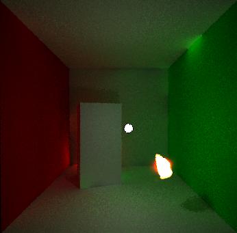
A second approach that produced a noticeably better picture was done by revolving the intensity by not the color. The color was kept as an orthogonal projection along the z-axis of the volume.
revolving the intensity but keeping the color orthogonal to the z-axis of
the bounding box of the volume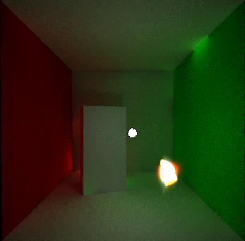
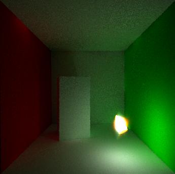
Putting the light inside the flame would have made it perfect, but that had some unfortunate side effects due to the light passing through an absorbing volume...
light inside the flame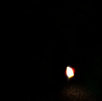
To remedy the situation, we tried a hack by putting the light a wee bit behind the flame so it would look like it was coming from the flame, but wouldn't have the darkness side effect...
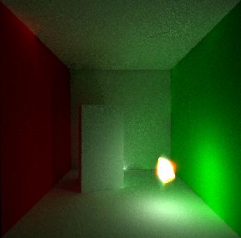
In the end, (after the rendering competition) we just decided to just zero out the absorption coefficient and it didn't turn out too bad...
Translucency
The translucency algorithm we used was from the paper by Jensen and Buhler
from 2002, A Rapid Heirarchical Rendering Technique for Translucent Materials.
This algorithm works as follows:
In the preprocessing stage, create
sample points on all the translucent objects. In the paper they used uniform
sampling. However, since a weight is assigned to each sample point, uniform
sampling isn't required. We sampled at the rate of about 1 point per 1 square
unit area of our candle object.
The next step is also a preprocessing
step. After the photon map is created, it is used to create irradiance estimates
at each of the points on the surface of the object.
Now we begin the
rendering process. The important idea here is that due to the translucency,
light exiting at the intersection point may be coming not only from light
directly hitting that point, but also from light hitting other spots on the
surface. This light could be scattered inside the object and exit at our
intersection point. To simulate this, the sample points we created earlier are
used. For each of these points, the dipole diffusion approximation is
calculated. The radiant exitance at the intersection point x is:
where dMo(x) is
calculated as
See the 2002 Jensen paper for details of these equations, but some
important things to note are Ep and Ap which represent the irradiance at the
sample point P and the area associated with the sample point P respectively. One
more important piece is the exponential falloff with distance that is seen in
the second equation. This approximation is calculated for all the sample points
and summed to give the radiant exitiance (and after a quick conversion radiance)
at the intersection point. The 2002 Jensen paper exploits the exponential
falloff in space to speed up the calculation. Their method uses octrees to group
points spatially and uses a error term based on the area represented by the
sample points and their average distance from the intersection point to decide
whether to recurse into the octree. Unfortunately as of competition time we had
some errors in that code and weren't able to use it.
One last note. The
single scattering term wasn't computed since the multiple scattering dominates
with large values of the scattering coefficient is much larger than the
absorbtion coefficient as it was in our parameters.
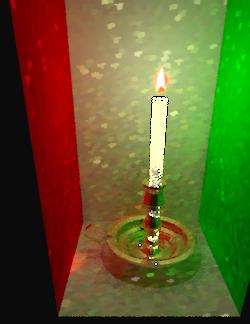
This was with fewer samples on the surface of the wax, it looks almost right,
but there is a black stripe that should not appear.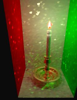
Here is one of the pictures we made with a mirror on the back wall. While
somewhat interesting, we decided against having it in our final
pictures.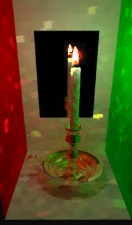
Stuff we wanted to do but didn't have time:
We wanted to try to simulate the melting of the wax; however we ran out of
time and weren't able to implement this. From some brief research we did,
metaballs would seem to be a useful for creating the shape of the drips. We
didn't do much research into the physical properties of melted wax, but we
assume it could be simulated as a normal liquid with certain vicous
properties.
We also had a vision for a more artistic scene, but never made or found a model of a face to render. This would have also required tinkering to find suitable parameters for the translucency paramters of the skin. At one point we added a mirror to the scene, but it increased our rendering time considerably and didn't add much to the scene in our opinion.
Challenges:
As expected quite a bit of time was spent reading the papers and trying to understand the mathematics involved. We discovered that our understanding of the light field and transport equations needed some review and a more solid foundation before we understood the equations in the paper.
Previous work on fire:Duc Quang Nguyen, Ronald Fedkiw, and Henrik Wann Jensen
"Physically Based
Modeling and Animation of Fire"
ACM Transactions on Graphics (SIGGRAPH'2002),
vol. 21, issue 3, pages 721-728, San Antonio, July 2002
Lamorlette, Foster:
"Structural Modeling of Flames for a Production
Environment",
in Proc. SIGGRAPH 2002
(Shrek paper )
Previous work on translucent materials (e.g. wax and skin):
Henrik Wann Jensen and Juan Buhler
"A Rapid Hierarchical Rendering
Technique for Translucent Materials"
ACM Transactions on Graphics
(SIGGRAPH'2002), vol. 21, issue 3, pages 576-581, San Antonio, July 2002
Henrik Wann Jensen, Steve Marschner, Marc Levoy, and Pat Hanrahan
"A
Practical Model for Subsurface Light Transport"
Proceedings of SIGGRAPH'2001,
pages 511-518, Los Angeles, August 2001